64 LEDs, One Cube: How I Built a 4x4x4 NeoPixel LED Cube with Adaptive Brightness
A walkthrough of building a 4x4x4 NeoPixel LED Cube with four animation modes and automatic brightness adjustment via an LDR sensor, using Arduino and bare C++.
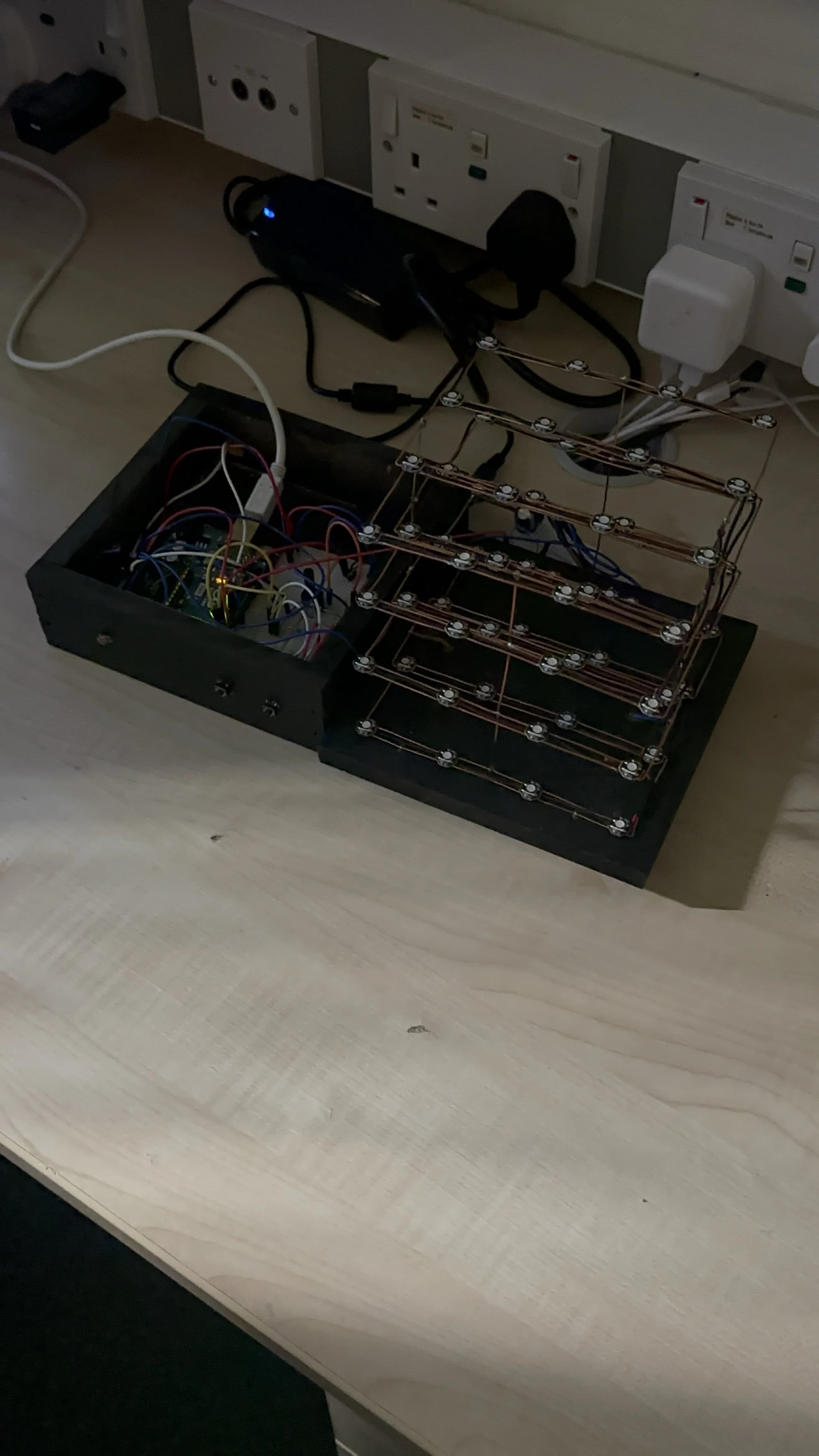
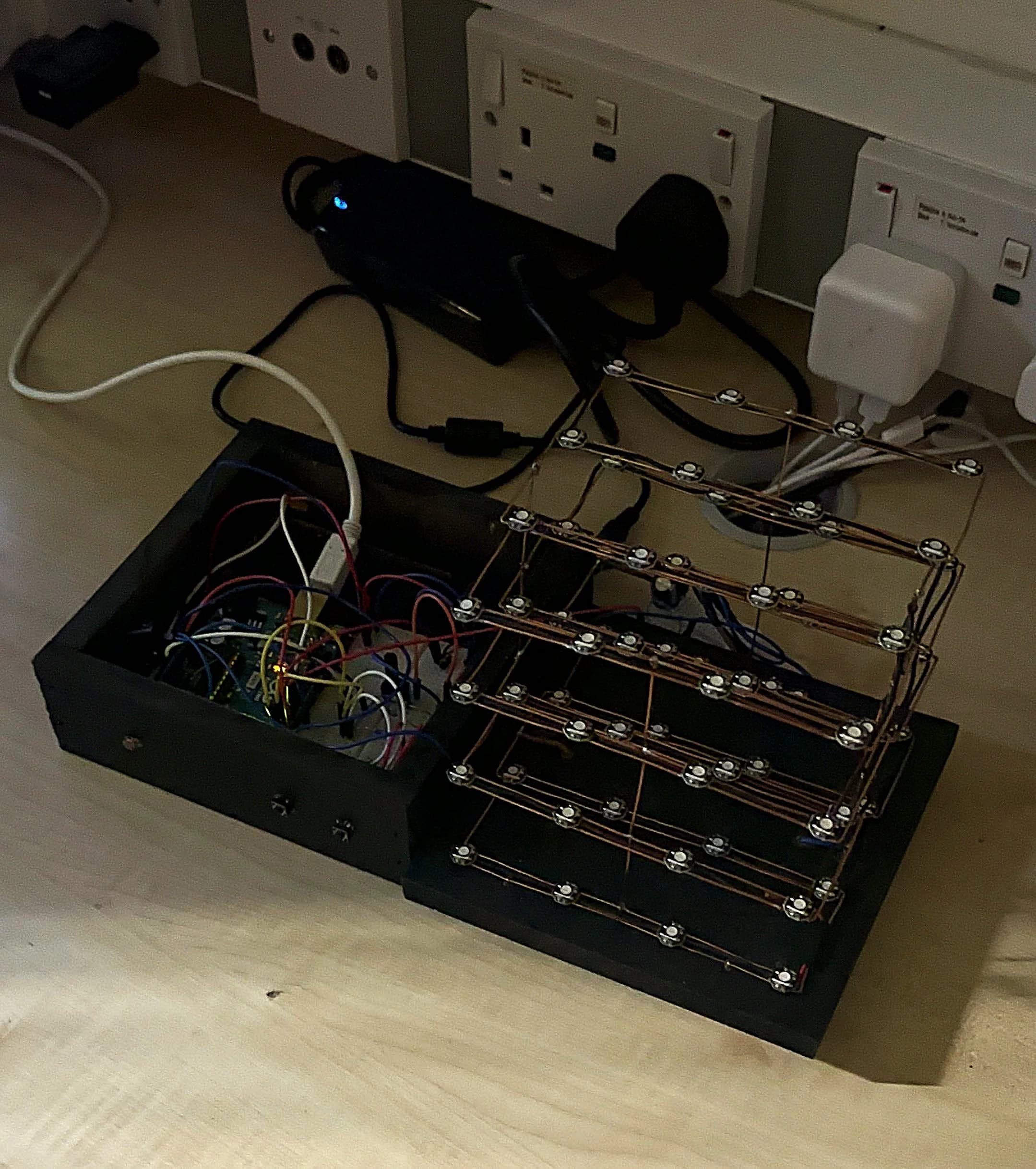
The finished 4x4x4 NeoPixel LED Cube - 64 WS2812B LEDs hand-soldered into a matrix
A WS2812B is an addressable RGB LED: each one contains a tiny built-in controller chip that lets you set its colour independently using a single data wire. You chain them together and send a 24-bit colour value for each LED in sequence. The chip handles the rest.
The NeoPixel LED Cube started as a university assignment and turned into something I am genuinely proud of. 64 individually addressable WS2812B LEDs, hand-soldered into a 4x4x4 matrix, controlled by an Arduino Uno with adaptive brightness and physical button controls. No pre-made cube kit. Built from scratch.
The Hardware
The cube uses 64 WS2812B LEDs arranged in four horizontal layers of 16 LEDs each. All 64 LEDs are chained on a single data line controlled by the Arduino Uno's digital output. The WS2812B is a self-contained RGB LED with an integrated driver chip, which means each LED only needs a single data wire in addition to power and ground. You send a 24-bit colour value for each LED in the chain and the chain self-propagates the data.
64 WS2812B addressable LEDs in a 4x4x4 layout
Arduino Uno (ATmega328P)
LDR (light-dependent resistor) for ambient brightness sensing
Two physical buttons: power toggle and mode cycle
5V DC power supply at 2A or above (required for full brightness)
Adafruit NeoPixel library for LED control
Power Budgeting
Power budgeting was one of the most important design decisions. Each WS2812B LED draws up to 60 mA at full white brightness. With 64 LEDs that is potentially 3.84 A. Running all LEDs at full white would require a substantial power supply and would generate significant heat. The solution was to cap brightness in software using the Adafruit NeoPixel library and never display full white on all LEDs simultaneously. In practice the cube draws well under 2 A during normal operation.
Animation Modes
The firmware implements four animation modes, cycled through using a physical button:
Colour Wipe: fills the cube LED by LED from bottom to top, cycling through colours
Smooth RGB Fade: all 64 LEDs smoothly transition through the full RGB spectrum simultaneously
Fire Effect: simulates a flame using randomised warm colours with upward propagation through the layers
Rainbow Cycle: each LED is offset in the colour wheel so the whole cube displays a rolling rainbow pattern
Adaptive Brightness with the LDR
The LDR reads ambient light via the Arduino's ADC on an analogue pin. The raw reading is mapped to a brightness value using Arduino's map() function. In bright environments the cube runs at higher brightness. In dim or dark environments it automatically reduces brightness to avoid being blinding. This runs in a non-blocking loop, sampling the LDR and updating the NeoPixel brightness value at regular intervals without interrupting the animation.
Serial Diagnostics
The firmware outputs real-time debug information over serial at 9600 baud: current animation mode, current brightness value and LDR reading. This was invaluable during development and makes it straightforward to verify the brightness scaling is working as expected.
The Fire Effect Algorithm
The fire effect was the most technically interesting animation to implement. It uses a two-dimensional heat array representing temperature at each LED position. Each frame, heat propagates upward with random variation and decays at a configurable rate. The heat value maps to a colour: deep red at low heat, orange in the mid range, bright yellow-white at maximum. The result is a convincing upward flame despite the algorithm being under 30 lines of C++.
Power budgeting was critical. Each WS2812B draws up to 60mA at full white. 64 LEDs at full brightness would draw 3.84A, far more than a USB port can supply and enough to cause visible flickering and colour shift. The solution was to cap brightness in software using the Adafruit NeoPixel setBrightness() function and to never run all LEDs at full white simultaneously. In practice during normal operation the cube draws well under 2A at 5V.
A 1000uF electrolytic capacitor across the 5V power rail is essential. Without it, the sudden current draw when LEDs switch state causes voltage spikes that can corrupt the WS2812B data line and produce random colour flashes. This is one of those details that is not in beginner tutorials but matters the moment you scale past a handful of LEDs.
What I Learned
Hand-soldering 64 LEDs into a 3D matrix is significantly harder than it looks. The physical construction took more time than the firmware. The main lessons: use flux, keep your iron tip clean and solder each joint fully before moving to the next. Cold joints on LEDs in the middle of the chain are very difficult to diagnose because the entire section after the fault goes dark. Testing each layer with continuity checks before stacking them saved significant rework time.
The WS2812B protocol is unforgiving of timing. The data signal uses specific high and low pulse widths measured in hundreds of nanoseconds. On an Arduino running at 16MHz this works reliably, but any interrupt that disrupts the timing mid-frame corrupts the entire frame. Disabling interrupts during LED updates was necessary for stable output.
Comments
Have a thought, correction or question? Sign in with GitHub - I read every comment and reply where I can.